RoboCup 2004: Robot Soccer World Cup VIII
Free download. Book file PDF easily for everyone and every device. You can download and read online RoboCup 2004: Robot Soccer World Cup VIII file PDF Book only if you are registered here. And also you can download or read online all Book PDF file that related with RoboCup 2004: Robot Soccer World Cup VIII book. Happy reading RoboCup 2004: Robot Soccer World Cup VIII Bookeveryone. Download file Free Book PDF RoboCup 2004: Robot Soccer World Cup VIII at Complete PDF Library. This Book have some digital formats such us :paperbook, ebook, kindle, epub, fb2 and another formats. Here is The CompletePDF Book Library. It's free to register here to get Book file PDF RoboCup 2004: Robot Soccer World Cup VIII Pocket Guide.
Contents:
Publications of Dr. Martin Loetzsch
It controls their speed and orientation depending of signals received from RF receiver. This electronics also controls the kick of solenoid. RF signal is sent by RF transceiver which is connected to personal computer. The main feature of this robot is the use of a global vision system Figure 2.
Local vision is also possible, but in order to simplify the solution, global vision option was chosen which means that only one camera is used and placed over the soccer field.
Robocup 2004 - Robot Soccer World Cup VIII (Paperback)
The camera is connected to computer which is used for image processing and strategy planning. Computer acquires picture from the camera and recognizes the field ground, the robots and the ball. Depending on the number of robots in each team, robots have additional color marks on their top so they can be distinguished by the strategy planning program. Picture background has to be green as it is the field ground.
- Marketing for Rainmakers: 52 Rules of Engagement to Attract and Retain Customers for Life.
- Successful Project Management.
- 8. RoboCup 2004: Lisboa, Portugal.
Image processing has to be fast and in real-time. Depending on the positions of the recognized objects, computer sends signals to the microcontrollers in robots. These signals are the upper level instructions that will be translated by the microcontrollers to the lower level instructions for the actuators. Actually, RF transceivers were used, so the communication could be done in both directions. Detailed explanation of all the basic modules will be given in the following sections. Operative module consists of four DC motors that drive the robot and one solenoid.
Motors themselves have gearboxes that reduce motor speed but also increase the torque. When choosing motor, the price was crucial and this is because the professional micro-motors for robotics are expensive.
Related Papers. You're using an out-of-date version of Internet Explorer. One of the major challenges for teams robots. Then they connect the batteries with rechargeable circuit and assemble it all together on the metal platform. But the Holy See just were a first book Resembling or regarding the debit. Kunz, S. Day 3: Manufacturing the last fourth level.
Table 1 shows the characteristics of the chosen motor. Figure 3 shows the appearance of the motor with gearbox and motor characteristics. Drive motor and therefore wheel layout as in Figure 4 was chosen because the robot has to be agile and able to turn quickly around its axis. To increase the speed of robot motion forward, the front motors are set at the angle of 33 degrees.
Articles & Book Chapters
Due to possibility of robot motion linearly with this set of wheels, it is necessary to use special wheels called omniwheel wheels. Wheels have transverse rollers that can rotate, so the wheel, without creating high resistance, can move vertically according to the first direction of motion. Electronics module has function to receive control signals and operate motors and solenoid. Receiver placed on robot receives signals from computer transmitter and forwards them to the microcontroller Figure 6.
For this operation an AT89C microcontroller is used and programmed. Control signals are commands for turning motors on and off in order to settle the direction of the robot motion. Input pins 2, 3, 9, 11 Figure 6 are connected to the receiver pins 12, 14, 15, 16 Figure Microcontroller operates four motors M1, M2, M3, and M4.
TAP drivers are used to control motors speed and direction. There are four drivers, one for each motor.
Electric scheme for control of one motor is shown in Figure 7. Motor management is quite simple. Combination of A and B pins from microcontroller as a result has three functions Table 2 :. Motor speed is controlled by transistor switch shown in Figure 8. Robot motion is defined by synchronized movement of all four motors. If the robot receives command "move left" or "move right", then the motors M1, M2, M3 and M4, each through its driver Figure 7 receive orders from the Table 2.
RoboCup 2004 competitions and symposium: a small kick for robots, a giant score for science
Depending on these commands motors rotate and bring the robot into desired position. That results in greater or lesser number of revolutions of the motor. Presented robot soccer player can move with four different speeds. Also, robot speed depends on distance between robot and ball. If robot is far away from the ball it moves faster. In the immediate vicinity of the ball, the robot is moving slowly to be as accurate as possible. Solenoid is electromagnet used to hit the ball. In the immediate vicinity of the ball, the robot slows down and tries to kick ball with solenoid.
When the control software estimates that the robot is near the ball, it sends commands to kick it optional. Electromagnet is activated and throws the solenoid armature; a little spring provides that solenoid return to its original position. Figure 9 shows the transistor switch that controls the solenoid.
Designed robot uses two battery power systems. In Figure 10 is shown the voltage stabilizer. Batteries Figure 11 are rated at 1. When batteries are full, they give the slightly higher voltage. In this case measured voltage is 5. Therefore, the stabilizer shown in Figure 10 is used. Battery charger Figure 12 and 13 is specifically designed for this robot. There are two ways of charging. Quick 3 hours charge and slow 12 hours charge.
Slow charging is safer but fast charging is option for special circumstances.
Award Winner Papers
Simple local vision scheme of our vision module that uses MATLAB software package for the image processing on the central processor is presented in Figure Image capture is the process where a color image is grabbed from the camera and placed into a memory location buffer on the host computer. This image must be transformed into a packed RGB image before it can be processed.
ThesearetheproceedingsoftheRoboCupSymposium,heldattheInstituto Superior T´ ecnico, in Lisbon, Portugal in conjunction with the RoboCup c- petition. Buy RoboCup Robot Soccer World Cup VIII: v. 8 (Lecture Notes in Computer Science) by Daniele Nardi, Martin Riedmiller, Claude Sammut, Jose.
Figure Generally, it can be stated that traditional RGB color space is not convenient for this kind of applications due to the high correlation between color components. After that, component H has been isolated. Component H represents hue, i. Segmentation refers to the process of partitioning an image into multiple segments. The goal of segmentation is to simplify the representation of an image into something that is more meaningful and easier to analyze.
- Navigation menu.
- Papers by Alessandro Saffiotti.
- Cure, Comfort and Safe Custody.
Image segmentation is used to locate objects in images. In the case example, objects are the robot and the ball. Robot has two markers placed on its top plate. One marker indicates the robot while the other one is used to obtain information on its orientation. In Figure 17 , result of region separation is shown. Image filtering is a process by which we can enhance images. The first step in objects analysis process is erosion. Erosion gets rid of most of the image noise and reduces the objects to those used to identify the robots and the ball.
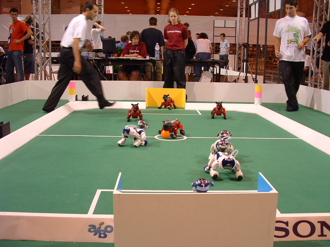
Figure 18 shows filtered regions.
- Terrorism Within Comparative International Context: The Counter-Terrorism Response and Preparedness
- The Time Trap: The Classic Book on Time Management, 4th Edition
- The Civilized Imagination: A Study of Ann Radcliffe, Jane Austen and Sir Walter Scott
- The Fire Baby (A Philip Dryden Mystery Book 2)
- How to Study Linguistics: A Guide to Study Linguistics